
Building a D&RGW 6000 Series Flatcar
by Harry Hungate
Last updated March 29, 2020 -- almost complete
Denver and Rio Grande Western Series 6000 Wooden flat car in 1/5 scale
This builder's blog will take you through the construction of a 1/5 scale model of a flat car originally built by the Denver and Rio Grande Western Railroad in Colorado. This flat car will be used to carry a horizontal propane tank to provide boiler fuel for my 1/5 scale Fitchburg Northern live steam locomotive. The propane tank will be concealed beneath a cargo of rough cut timbers which will also serve as a passenger seat. The dimensions of the flat car are true 1/5 scale as taken from original blue prints obtained through the generosity of the volunteers at the Colorado Railroad Museum in Golden, Colorado. One exception is that I shortened the length of the flat car so it would fit in the cargo area of our Toyota RAV4. It is forty-five inches long excluding the couplers.
An example of the original blue prints.
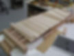
Rounding up the wood for the flat car was the first task. My sister's husband offered a huge plank of heart poplar. Note that this is not the poplar that you might find at Home Depot or Lowe's. This is heart poplar, a beautiful and sturdy species of wood, and it turns out that this is exactly what was specified for the original flat cars.
Our community workshop at Cypress Village in Jacksonville, Florida has a complete wood and metal shop. We had recently upgraded our ancient Craftsman table saw to a new five horsepower Powermatic table saw. It is an absolute joy to use and I set about reducing the plank of heart poplar per the scaled down dimensions.
A combination of planing and sanding yielded the exact dimensions desired.
The next task was to design and construct the two bolsters. These are the metal frames that provide the pivot points for the two four-wheeled trucks. C-1018 cold rolled steel was the material of choice. It is relatively inexpensive, easy to work, and accepts silver solder readily.
The bolsters required some judicious adjustments to the original dimensions, but are very strong and realistic in appearance. Considerable notching and adjusting was required to fit the sills into the bolsters. Once that bolsters were completed and painted, I assembled them and the stringers.
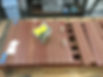
I made a jig to serve as a drill guide in locating the holes for the dowels in the stringers and end sills. Titebond III glue was liberally applied to the parts and multiple clamps were used to hold the parts square until the glue set. Unfortunately, I neglected to notice that the workbench top was not nearly flat enough, resulting in a wracked frame. Nothing for it except to cut the end sill free from one end and start over. That explains the
next photo. I had to remove the deck planks and reattach one end sill while clamping the flat car securely to attain flatness.


Maple deck planking being trial fitted prior to being ship-lapped.
Wood dowels and Titebond III glue hold the end sills securely to the joists.
The decking is hard maple salvaged from drawer fronts from our kitchen modernization project. I ship-lapped the maple planks as per the prototypical practice. This results in a much stronger deck. Each plank is held in place with four socket head stainless steel bolts. This is not according to prototypical practice, but it is practical and acceptable to me.
Note the business card spacers between each deck plank.
I started the planking from each end and worked toward the middle. The end planks are ship-lapped only on the inner sides. The center plank (king plank in marine terms) was adjusted to fit the remaining space. The difference in width is hardly noticeable.
The two queen post beams run cross-ways and provide for mounting the eight queen posts which serve to transfer the load from the stringers to the four truss rods which run from sill to sill. The queen posts are attached with miniature hex head bolts. The truss rods are tensioned with turnbuckles and also serve to help prevent the car from being pulled apart.
Queen posts and beams and truss rods installed.
This completed the wood-working phase of the project.
Installing the truss rods required some adjustments including the truss rod guides in the bolsters. I made these from Delrin as it is very strong, easy to machine, does not rust and provides a low friction surface for the truss rods.
The truss rods are made from 1/4 inch diameter stainless steel rod with right and left hand threads for the turnbuckles. I purchased the un-threaded turnbuckle castings, the end washers, stake pockets and U-bolts, brake wheel and shaft supports, cutting lever brackets and retaining valve from Tom Artzburger: beautiful die-cast parts required very little or no cleanup.
Once the truss rods were installed I tightened them only finger-tight (or so I thought). You can imagine my dismay when I returned to the workshop the next morning to find the flat car curved like a banana! I loosened the turnbuckles and allowed the deck to relax. A spacer plank slipped through all four turnbuckles keeps them fixed--per prototypical practice.
The coupler pockets and draft gear required many hours of hack sawing, filing, silver soldering. I purchased the two cast iron coupler pockets and brass coupler castings from Allen Models and milled and filed them to shape. The end plates were made from C-1018 cold rolled steel. My photo collection of prototype rolling stock shows that end plates were quite rough and assumed shape and dimension sufficient to perform satisfactorily. I free-styled these as only the front is visible. What remains out of sight is sufficiently strong. This car will not likely ever be pulled apart.


A bolster is visible in the background behind the wheels. The truck pivot pin and support is in the center of the bolster. Delrin truss rod guides are being fitted in this photo: on the left the Delrin guide is in place in the bolster and the one on the right will be fitted next.
Completed coupler pocket and end plate with coupler and trucks trial fitted.
Now it was time to fit the two trucks. The prototype equipment had arch-bar trucks, but I decided to upgrade to a more modern (from the 1940's) design. I purchased two ready-to-run Bettendorf freight car trucks from Tom Bee. Tom delivered the trucks and my Ridge Locomotive Works boiler to me at the February 2019 Winter Meet at Ridge Live Steamers in Dundee, Florida. Tom is a real gentlemen and a genuine pleasure with whom to do business.
The trucks were disassembled, degreased and primed and painted with Rustoleum red oxide. Tom has an air brake option for his trucks, but I needed vacuum operated brakes to match those on my tender. I purchased the eight brake shoes and arms from Tom and designed my own vacuum brake system. I purchased two "choke motors" from Rock Auto Parts and adapted them as required. The end result is very satisfactory as I can lock all eight wheels with a very light vacuum. In actual operation the vacuum will be developed with a steam ejector in the cab of the locomotive.
Completed truck and vacuum brake system.
The trucks required some adjustments on the dimensions of the center pin spacers to obtain the correct clearance to the bolsters. A grease fitting in the bottom of the center pin allows for periodic lubrication. The brake hoses and end fittings will be added later.
Next came the stake pockets. I made a drilling jig to accurately locate the holes for the two U-bolts which attached the stake pockets to the outer stringers. Another judgement call was required in determining the spacing for the stake pockets as I had deviated from the proper scale length of the car. A visually pleasing spacing was obtained, with the casualty being insufficient space to install the foot steps and side hand rails near each end of the car. In actual use these are early casualties during derailments, so I am not too disappointed to omit them.
Insert photo of drilling holes for stake pockets.
Stake pockets and hand rails installed.
I made up four hand rails from 1/16 inch brass rod and scraps from my junk box. These were bolted to the end sills with miniature hex head bolts.
Cutting levers were bent from 1/8 inch stainless steel rod and installed with the Tom Artzburger brackets.
Next came the brake wheel and shaft supports and ratchet wheel and pawl, also from Tom Artzburger.
The brake system retaining valve is only for show. It does not actually operate.
Brass tubing end-of-car fitting for vacuum brakes. Note square nuts made from half inch bar stock.
The vacuum brake hose end fittings were made from 3/16 inch brass tubing and brass hex stock, soft-soldered together and drilled and tapped into the end plates. Automotive vacuum hose connects the end fittings and vacuum motors. The rear end-of-car fitting is capped.
Flat car in service with HK Porter 0-4-0T at Northeast Florida Railroad, Palm Coast, FL Nov 2019.
The battery box contains a small 12 volt vacuum pump for the brakes.


